The only constant we have is change.
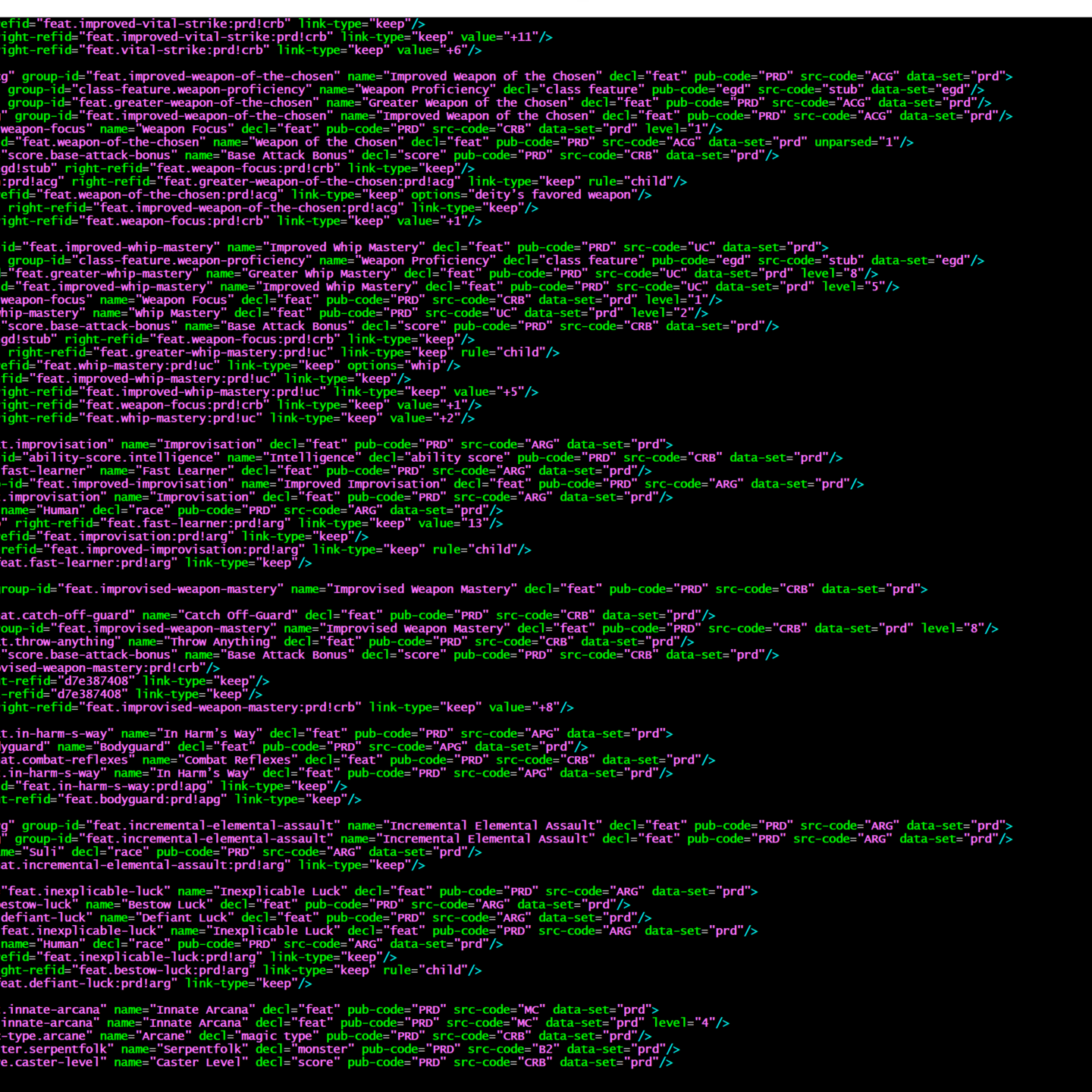
There was a major change to how I represent data in my workflow. Overall this is a good thing: it gives me more flexibility in what I can capture and model cleanly, it lets me more precisely match things when I’m searching, and it is encoded in a way that removes some of the challenges I’d previously had.
That it broke everything downstream is something of an annoyance, but still worth it.
The big thing I’m working on now is rebuilding my diagram construction code. The Echelon Reference Series has many diagrams, and I want to take advantage of the recent changes.
- First, searches have gotten much better. I can get much more reliable joins, with fewer errors and requiring much less intervention.
- Second, I capture metadata about the prerequisites better, making it so I can more readily identify and adjust prerequisites that could otherwise not be resolved. For instance, the other day I found a prerequisite whose text matched two target objects with the same precedence. I now know to adjust the source text so it can find the right one… or I could create a new object specifically to serve as the prerequisite. Now that I know, I can fix it.
- Third, frankly, I know more now than I did when I first wrote the code, and can do a better job.
The new process is quite a change from the old one, but I think worth it.
Old Process
The old implementation for the diagrams was… not actually complicated in and of itself, but I’d made a couple of decisions that made my life (and the diagrams) more difficult than needed. At its base, the process was:
- For each object that has prerequisites or is prerequisite of another,
- Find all children (objects that refer to this object) to the leaf level (i.e. until there are no more children). The starting object might be the leaf object.
- Work backward, resolving all prerequisites until all parent objects have been identified, back to their roots.
- Remove duplicate nodes (objects) and edges (prerequisite links between nodes).
- Cull edges that are satisfied by transitive relationships (i.e. given “A -> B -> C;” and “A -> C;”, the latter can be culled because C’s need for A is satisfied via B).
Once I’ve got these diagrams defined, they can be written out as DOT files and PNG files created, to be used as the basis for the diagrams that get redrawn into the books.
New Process
The new process is a little more complicated in that it spends some time normalizing the data first, but after that it should get much simpler.
Simple Description
At its base, pretty straightforward.
- Identify and normalize all relevant nodes.
- Identify and normalize all relevant edges.
- For each node, create a diagram with the node, all prerequisite nodes, all child nodes, and the minimal edges needed to draw the diagram.
Detailed Description
In detail… lots of steps, but mostly easy.
- For each object that has prerequisites or is prerequisite of another
- Generate a node to represent the object.
- For each prerequisite of that object,
- If that prerequisite is an ‘or’ or ‘and’ prerequisite, generate a node (marked as a prerequisite of the parent object), and process child prerequisites. [slight lie here — process children first, then create the ‘or’/’and’ node, in order to get a canonical string describing the structure; still assign a surrogate ID, but I’ll want to collapse this mess later.
- If that prerequisite is has a refid (i.e. points at a specific object), create an edge connecting the reference object to the parent (object or ‘or’/’and’ node).
- If that prerequisite does not have a refid (i.e. could not be resolved), create a dangling edge (points at the parent node but has no referenced object).
- At this point all objects and prerequisites have been turned into nodes and edges. Time to clean up.
- All object nodes already are unique, nothing to do here.
- Aggregate all ‘or’ and ‘and’ prerequisite nodes by canonical string, and output one unique prerequisite node for that string. For instance, I’ve seen “darkvision or low-light vision” (‘or’ node with two referenced objects) result in two distinct ‘or’ nodes each connecting to darkvision and low-light vision… in a single diagram. This should be a single unit.
- Cull all transitive edges: for each edge, if the object pointed to by the right-refid has any edges with a left-refid that points at an object that has a prerequisite with the same left-refid as this one, this one can go.
- Time to generate diagrams. Every object node will have a diagram, so no need to be selective. For each object node:
- Create a diagram object containing
- The base object node, then recursively
- (recursively) All prerequisite edges and nodes back to the beginning.
- (recursively) Edges to child object nodes:
- If the right-refid points at an object node, copy this node.
- If the right-refid points at an ‘or’/’and’ node, follow the chain until it reaches the object-node and create that edge in this diagram (only), marked ‘optional’.
- The object node ultimately pointed at.
- For each node, if there are more potential prerequisites than are connected (whether because there are unresolved prerequisites, or prerequisites were ignored because they are not relevant to the focal node of the diagram), mark the difference as a ‘hidden prerequisite count, to be rendered on the node.
- Create a diagram object containing
This has a couple extra steps at the start, but once the data is cleansed I no longer need to use convoluted XPath referencing to find the connections.
New Workflow Step: Pics
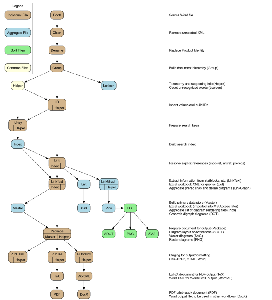
One of my peculiarities, I find it very satisfying when a process has steps with monotonically increasing names. In this case, I’ve implemented the LinkGraph step that runs after the Link step, and does the transformation described above. Next, I’m adding the Pics step that will take the diagrams defined in the LinkGraph step, generate a DOT file for each, and list each in the resulting output XML file. That is, master-pf1-all.pics.xml contains links to all the DOT files (and expected rendered files) in the set. This may be of use later, input into the Pub* steps.
After this, naming convention breaks down because I’m working with individual files and I want the extensions to match the system expectations. Ah well, that happens at the end of the chain.

Closing Comments
The code for this really didn’t take long to write… at least, with what I know now. Getting to the point where this is true has taken quite some time — about ten years, really, though that includes much downtime.
Still, I think it’s been worth the trouble. The utility of the diagrams, and now (hopefully!) being able to better automate the process as a whole, can make the books much more useful.
